- NC: [circuit] Not Connect/No Connection. It means this pin doesn't need to connect.
- GPIO: [circuit] General Purpose Input / Output. Those are programmable data input and output ports
- ADC: [circuit] Analog to Digital Converter, is a very useful feature that converts an analog voltage on a pin to a digital number. By converting from the analog world to the digital world. Not every pin on a microcontroller has the ability to do analog to digital conversions. On the Arduino board, for example, these pins have an ‘A’ in front of their label (A0 through A5) to indicate these pins can read analog voltages. reference: https://learn.sparkfun.com/tutorials/analog-to-digital-conversion/all
- DAC: [circuit] Digital to Analog Converter
- PWM: [circuit] pulse-width modulated. The PWM seems to imply DAC functionality, but it just controls the PWM output with a function called analogWrite(). https://www.instructables.com/id/Analog-Output-Convert-PWM-to-Voltage/
Showing posts with label Technique. Show all posts
Showing posts with label Technique. Show all posts
Sunday, 18 November 2018
[Technique] Terms Summary
Friday, 16 November 2018
[Technique] How to Install the ESP32 and ESP8266 Board in Arduino IDE

1. Brief Introduction
Arduino is an open-source electronics platform based on easy-to-use hardware and software. Thanks to its simple and accessible user experience, Arduino has been used in thousands of different projects and applications. It runs on Mac, Windows, and Linux. Moreover, it is extremely compatible with many microcontrollers. So with this post, I take NodeMCU board as an example to show you how to install outside boards on Arduino IDE
2. Installing Process
- Download the Arduino IDE
- Open the preferences window from the Arduino IDE. Go to File> Preferences

- Enter URL into the “Additional Board Manager URLs” field as shown in the figure below. Then, click the “OK” button. For ESP32, the json link is https://dl.espressif.com/dl/package_esp32_index.json; for ESP8266, the json link is http://arduino.esp8266.com/stable/package_esp8266com_index.json.

- Open boards manager. Go to Tools > Board > Boards Manager…

- Search for ESP32 or ESP8266 and press install button:

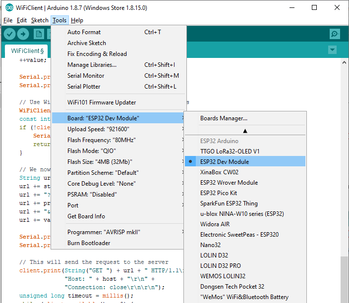
- Select your Board in Tools > Board menu. For ESP32 DEVKITV1, the board should chooseESP32 Dev Module; For ESP8266(CP2102), the board should choose

- The installment is finished. However, before you can start your journey with ESP boards in Arduino IDE. You really need to know their pins layout. For ESP32 ESP32: https://www.instructables.com/id/ESP32-Internal-Details-and-Pinout/. For ESP8266: https://circuits4you.com/2016/12/14/esp8266-pin-diagram/
ESP8266 Pin_layout

ESP32 Pin_layout

Thursday, 15 November 2018
[Technique] ESP32 Bluetooth Low Energy

1. Introduction
Bluetooth Low Energy (BLE) is one kind of wireless protocol. This blog will give you an overview of BLE, specifically how data is organized in BLE, how devices advertise their presence and how to establish communication between them.
1) Generic Access Profile
GAP is used to control the connections and advertising in BLE devices. Specifically,
- it determines the roles of devices (Peripheral devices or Central devices). The peripheral device usually acts as the Server or the Slave and The central device acts the Client and the Master.
- There are two ways to send advertising out with GAP. Peripheral devices advertise and central devices send Scan Response Data.
- A peripheral will set a specific advertising interval, and every time this interval passes, it will retransmit its main advertising packet. If a listening device is interested in the scan response payload (and it is available on the peripheral) it can optionally request the scan response payload.

- The Broadcast Network Topology shows as below. One peripheral can communicate with multi central devices but it only connects one central device at a time. As soon as a peripheral connects to a central device, it will stop advertising itself and other devices will no longer be able to see it or connect to it until the existing connection is broken.

2) Generic Attribute Profile
GAPP defines the way that two Bluetooth Low Energy devices transfer data back and forth using concepts called Services and Characteristics. It makes use of a generic data protocol called the Attribute Protocol (ATT), which is used to store Services, Characteristics and related data in a simple lookup table using 16-bit IDs for each entry in the table. Before GAPP works, GAP must be passed to enable connect.
- Once connecting, the Connected Network Topology is shown below. The Two-way communication is established between the central device and peripheral devices. But the central device can only connect one peripheral device at a time.

- Then a server/client relationship is built. So the data exchange process between a peripheral (the GATT Server) and a central device (the GATT Client) is shown:
- The GATT data structure can be illustrated as below: the profile stands for a collection of Services and it doesn't actually exist. Service, as the name suggests, stands for one kind of action. It is distinguished by the UUID. A service usually contains one or multi-characteristics. Characteristic is the lowest level concept in GATT transactions. If we see Service is the name of an action, the characteristic is the executor of this action. Similarly to Services, each Characteristic distinguishes itself via a pre-defined 16-bit or 128-bit UUID. Descriptors are defined attributes that describe a characteristic value. It means descriptors are used to set the content of each characteristic.

- An example of how the GATT data structure works: If you want to buy some potato chips. The Service is kind of like a grocery store, Walmart for example. Inside this Service (Walmart) there are many Characteristics which can be thought of different good sections (e.g. snack section, canned food section). For potato chips, you will choose the snack section. Then the Descriptors which are attributes of Characteristics can be thought of as some brands of potato chips in the snack section of Walmart. If the value of the Descriptor is 'Pringles', it means you pick up some Pringles potato chips.
2. BLE communication
1) BLE Serial Port Profile (SPP)
BLE serial port is based on SPP and used for establishing serial communication between BLEs, e.g. between Bluetooth modules, Bluetooth modules, Bluetooth adapters, and Bluetooth modules and PDAs and your computers.
2) Communication Structure
Before communicating, we will use two different characteristics, TX and RX under the same "service" on both ends to send data to and receive data via these two channels between two ends. The server "notifies" the client via the TX characteristic UUID and data is sent to the server and received via the RX characteristic UUID. However, as the TX on one end connects the RX on the other end, the UUID's of TX and RX are swapped on both ends.
3) Communication Process
More information can refer to the sources of ESP32_BLE_Arduino: https://github.com/nkolban/ESP32_BLE_Arduino/tree/master/src
- Create the BLE Device using 'BLEDevice::init("");'. Then advocate roles for the created BLE device: BLEServer, BLEScan and BLEClient. Here are some source codes to create a BLE server with Service and Characteristic:
#define SERVICE_UUID "4fafc201-1fb5-459e-8fcc-c5c9c331914b"
#define CHARACTERISTIC_UUID "beb5483e-36e1-4688-b7f5-ea07361b26a8"
BLEDevice::init("MyESP32");
BLEServer *pServer = BLEDevice::createServer();
pServer->setCallbacks(new MyServerCallbacks()); //set callback to get the status of BLE connection
pServer->setCallbacks(new MyServerCallbacks()); //set callback to get the status of BLE connection
BLEService *pService = pServer->createService(SERVICE_UUID);
BLECharacteristic *pCharacteristic = pService->createCharacteristic(
CHARACTERISTIC_UUID,
BLECharacteristic::PROPERTY_READ |
BLECharacteristic::PROPERTY_WRITE |
BLECharacteristic::PROPERTY_NOTIFY |
BLECharacteristic::PROPERTY_INDICATE
BLECharacteristic::PROPERTY_WRITE |
BLECharacteristic::PROPERTY_NOTIFY |
BLECharacteristic::PROPERTY_INDICATE
);
//specially, when the characteristic is created to notify data (no need for receiving data), we have to create a descriptor for characteristic by using: where BLE2902(), the Client Characteristic Configuration descriptor defines how the characteristic may be configured by a specific client.
// Create a BLE Descriptor
pCharacteristic->addDescriptor(new BLE2902());
- Data Transfer Methods
There are four basic operations for moving data in BLE: read, write, notify and indicate. https://www.silabs.com/community/wireless/bluetooth/knowledge-base.entry.html/2018/05/30/ble_basics_masters-i4n9
- If the client needs to send data to the server, use write.
- If the client needs to get data from the server on-demand (i.e. polling), use read.
- If the server needs to send data to the client without the client requesting it first, use notify or indicate. (The client must subscribe to these updates before any data will be transferred.)
- The server cannot pull data from the client directly. If this is necessary, the server must use notify or indicate to send pre-arranged request data to the client, and then the client may follow up with a write operation to send back whatever data that the server needs.
- Therefore, generally, the property of characteristic for the server sending data is usually BLECharacteristic::PROPERTY_NOTIFY | BLECharacteristic::PROPERTY_INDICATE; the property of characteristic for the server (actually, when the server is receiving data, it can be imagined as a client) receiving data is usually BLECharacteristic::PROPERTY_READ | BLECharacteristic::PROPERTY_WRITE
- Callback function
The Callbacks are classes of functions used to handle follow-up things after each transaction. For example, on BLE server end, there is BLEServerCallbacks to handle the connection status. And on BLE client end, there is a corresponding class, BLEClientCallbacks, to handle related things. Moreover, the service and the characteristic all have their own callback functions.
bool oldDeviceConnected = false;
format: class MyServerCallbacks: public BLEServerCallbacks {}
bool deviceConnected = false;bool oldDeviceConnected = false;
class MyServerCallbacks: public BLEServerCallbacks {
void onConnect(BLEServer* pServer) {
deviceConnected = true;
};
void onDisconnect(BLEServer* pServer) {
deviceConnected = false;
}
};
- Initiate the service and characteristic, then start advertising. To connect other BLE client devices, the server needs to advertise periodically. Once the connection which is triggered by the client built, the server stop advertising and only communicate with the connected client. The advertising codes are as follow.
uint8_t value = 0; //globe variable
pCharacteristic->setValue(&value, 1); //each Characteristic has a value.
// Start the service
pService->start();
// Start advertising
pServer->getAdvertising()->start();
- Use callback functions to deal with the message after building the connection.
4) Demonstration
- On ESP32 BLE end: Create two characteristics, RX and TX, for receiving and transmitting the data between ESP32 (server) and your mobile device (client)
/*
Based on Neil Kolban example for IDF: https://github.com/nkolban/esp32-snippets/blob/master/cpp_utils/tests/BLE%20Tests/SampleServer.cpp
Ported to Arduino ESP32 by Evandro Copercini
*/
#include <BLEDevice.h>
#include <BLEUtils.h>
#include <BLEServer.h>
#include <BLE2902.h>
// See the following for generating UUIDs:
// https://www.uuidgenerator.net/
#define SERVICE_UUID "6E400001-B5A3-F393-E0A9-E50E24DCCA9E" // UART service UUID
#define CHARACTERISTIC_UUID_RX "6E400002-B5A3-F393-E0A9-E50E24DCCA9E"
#define CHARACTERISTIC_UUID_TX "6E400003-B5A3-F393-E0A9-E50E24DCCA9E"
BLEServer* pServer = NULL;
BLECharacteristic* pCharacteristic_TX = NULL;
BLECharacteristic* pCharacteristic_RX = NULL;
bool deviceConnected = false;
bool oldDeviceConnected = false;
uint8_t sending_value = 0;
//monitoring the connection status
class MyServerCallbacks: public BLEServerCallbacks {
void onConnect(BLEServer* pServer) {
deviceConnected = true;
};
void onDisconnect(BLEServer* pServer) {
deviceConnected = false;
}
};
//Dealing with the data from the client
class MyCallbacks: public BLECharacteristicCallbacks {
void onWrite(BLECharacteristic *pCharacteristic) {
std::string value = pCharacteristic->getValue();
if (value.length() > 0) {
Serial.println("receiving data from the client");
Serial.print("New value: ");
for (int i = 0; i < value.length(); i++)
Serial.print(value[i]); //here you can make some judgement about the receiving data
//and trigger some other actions.
Serial.println();
Serial.println("*********");
}
}
};
void setup() {
Serial.begin(115200);
Serial.println("Starting BLE work!");
BLEDevice::init("MyESP32");
pServer = BLEDevice::createServer();
pServer->setCallbacks(new MyServerCallbacks()); //set callback to get the status of BLE connection
BLEService *pService = pServer->createService(SERVICE_UUID);
//Create two characteristics: RX (receiver) and TX (transmitter)
//this is TX charateristic
pCharacteristic_TX = pService->createCharacteristic(
CHARACTERISTIC_UUID_TX,
BLECharacteristic::PROPERTY_NOTIFY |
BLECharacteristic::PROPERTY_INDICATE
);
// Create a BLE Descriptor
pCharacteristic_TX->addDescriptor(new BLE2902()); // for each notify Characteristic, this step is neccessary
pCharacteristic_TX->setValue(&sending_value, 0); //give the variable an initial value. this varible can be other type.
// this is an interface we can insert our data from sensor or other devices
// to transmit to the mobile BLE client.
//this is RX charateristic
pCharacteristic_RX = pService->createCharacteristic(
CHARACTERISTIC_UUID_RX,
BLECharacteristic::PROPERTY_READ |
BLECharacteristic::PROPERTY_WRITE
);
pCharacteristic_RX->setCallbacks(new MyCallbacks()); //this callback will be called when data is received by this server
pCharacteristic_RX->setValue("Hello World");
// Start the service
pService->start();
// Start advertising to search surounding clients
pServer->getAdvertising()->start();
Serial.println("Characteristic defined! Now you can read it in your phone!");
}
void loop() {
// put your main code here, to run repeatedly:
// notify changed value
if (deviceConnected) {
Serial.println("BLE is connecting");
pCharacteristic_TX->setValue(&sending_value, 1);
pCharacteristic_TX->notify();
Serial.print("notifying: ");
Serial.println(sending_value);
sending_value++;
delay(10); // bluetooth stack will go into congestion, if too many packets are sent
}
// disconnecting
if (!deviceConnected && oldDeviceConnected) {
delay(500); // give the bluetooth stack the chance to get things ready
pServer->startAdvertising(); // restart advertising
Serial.println("start advertising");
oldDeviceConnected = deviceConnected;
}
// connecting
if (deviceConnected && !oldDeviceConnected) {
// do stuff here on connecting
oldDeviceConnected = deviceConnected;
}
delay(200);
}
- On the mobile device end: Firstly, downloading the BLE test apk; then following the introduction below.
- Click "+" to connect a new BLE

- Scan surrounding available BLE devices

- Choose the BLE device named "myESP32"

- Click the connect and once state turns True, two BLE devices connect.

- Choose "PROPERTY_NOTIFY", then you select the corresponding characteristic to receive data.

- Choose "PROPERTY_READ" or "PROPERTY_WRITE", then you select the corresponding characteristic to send data. Enter the string in the red area and click SEND.

Tuesday, 13 November 2018
[Technique] Three most common communication protocols: (1) UART
Universal Asynchronous Receiver/Transmitter (UART) communication protocol
1. Brief introduction
A universal asynchronous receiver-transmitter (UART /ˈjuːɑːrt/) is a computer hardware device for asynchronous serial communication in which the data format and transmission speeds are configurable. UART communication protocol is only used bwteen MCUs or MCUs and computers.
More information refers to http://www.circuitbasics.com/basics-uart-communication/
More information refers to http://www.circuitbasics.com/basics-uart-communication/
2. How many serial ports in the Arduino boards?
Different Arduino boards are different from each other.- For Uno, there is only one hardware serial port which is used for USB communication. On the board, there is another pair of pins for serial communication. 0 (RX) and 1 (TX) are used to receive (RX) and transmit (TX) TTL serial data. These pins are connected to the corresponding pins of the ATmega8U2 USB-to-TTL Serial chip. So it is not the hardware serial port.
- For Leonardo, there are two classes of hardware serial ports. The Serial class refers to USB communication; another hardware serial port--Serial1, 0 (RX) and 1 (TX), is used to receive (RX) and transmit (TX) TTL serial data using theATmega32U4 hardware serial capability.
- For Mega, there are three hardware serial ports: Serial 1: 19 (RX) and 18 (TX); Serial 2: 17 (RX) and 16 (TX); Serial 3: 15 (RX) and 14 (TX). Besides, on the board, the Serial, 0 (RX) and 1 (TX), is also connected to the corresponding pins of the ATmega16U2 USB-to-TTL Serial chip. These four serials are used to receive (RX) and transmit (TX) TTL serial data.
- In addition: All Arduino boards support software serial when there is no available serial ports.
- Supplement: This method of serial communication is sometimes referred to as TTL serial (transistor-transistor logic). Serial communication at a TTL level will always remain between the limits of 0V and Vcc, which is often 5V or 3.3V. A logic high ('1') is represented by Vcc, while a logic low ('0') is 0V. USB-to-TTL means the conversion from USB to TTL.
3. The difference between parallel communication and Serial communication.
- Parallel interfaces transfer multiple bits at the same time. They usually require buses of data - transmitting across eight, sixteen, or more wires. Data is transferred in huge, crashing waves of 1’s and 0’s.

- Serial interfaces stream their data, one single bit at a time. These interfaces can operate on as little as one wire, usually never more than four.

4. When communicating between the Arduino and the monitor, there are four formats for the output.
- No line ending: means there is no modifier following your input. input=output
- newLine: means there is a modifier '/n' following your input. output=input+'/n' (n--newLine)
- Carriage return: means there is a modifier '/r' following your input. output=input+'/r' (r-return)
- Both NL&CR: means there is a modifier '/n/r' following your input. output=input+'/n/r'
- For example: if you input 'e', the output are 101, 101 10, 101 13, 101, 13, 10 respectively.

5. Description of serial functions
6. SoftwareSerial Library
Please refer to https://www.arduino.cc/en/Reference/SoftwareSerial
7. Demonstration
- Serial communication between two Uno boards.

In this case, we take one as the sender and the other as the receiver. Different codes are uploaded to them. For the Uno board, there is only one hardware serial port. When we use Pin0 and Pin1 to communicate, the serial class is still Serial. The Uno will automatically detect the status of connection of Pin 0 and Pin 1 and send (Serial.write()) or receive (Serial.read()) the content if Pin 0 and Pin 1 are connected. At the same time, we can use Serial.print() to print the content on the computer monitor. These three different functions, Serial.write(),Serial.read() and Serial.print(), are very important in serial communication. The source code refers to https://iotguider.in/arduino/serial-communication-between-two-arduino-boards/.
- Software serial communication between three Uno boards.

There would be a situation where Pin 0 and Pin 1 are being occupied and you still need to use the serial connection with other devices like another Uno board (shown in the above picture). How to deal with this conflict? As mentioned above, all Arduino boards support Software serial communication. Therefore, in this demo, I will show how to use Software serial communication. The jumper wires connection is:

In this figure, Pin 10 and Pin 11 are the software serial ports used for connecting the right Uno Board. Here are some source codes (copy-> paste->upload):
- the left Uno
char mystr[5] = "Hello"; //String data
void setup() {
// Begin the Serial at 9600 Baud
Serial.begin(9600);
}
void loop() {
Serial.write(s);
delay(1000);
}
- the middle Uno
#include <SoftwareSerial.h>
// software serial #1: RX = digital pin 10, TX = digital pin 11
SoftwareSerial portOne(10, 11);
char mystr[10]; //Initialized variable to store recieved data
char c;
void setup() {
// Begin the Serial at 9600 Baud
Serial.begin(9600);
portOne.begin(9600);
}
void loop() {
Serial.readBytes(mystr,5); //Read the serial data and store in var
char c = portOne.read();
Serial.println(mystr); //Print data on Serial Monitor
Serial.println(c); //Print data on Serial Monitor
delay(1000);
}
- the right Uno
char s = 'B';
void setup() {
// Begin the Serial at 9600 Baud
Serial.begin(9600);
}
void loop() {
Serial.write(s);//Write the serial data
delay(1000);
}
- The output

- The usage of Software serial port
Generally, we can use Software serial ports whenever we want. But it would be best to use it when Pin 0 and Pin 1 are already used.
Sunday, 11 November 2018
[Technique] some information about the Google blog domain
To figure out the domain is not an easy thing. I don't know much before I started to use google blogger to share some interesting ideas. Generally, it will be enough to use the default domain provided by google blogger, like: xxx.blogspot.com. However, blogspot.com is walled by China. Therefore, I need to purchase a third-party domain to skip that problem.
One good news is that the third-party domain purchasing interface is already provided in the setting of google blog. You just need to click the link and pay for it. The cheapest domain is £10.
Another setting is the sub-domain. From some online information, the third-party domain we purchase support multi sub-domains, which means you can use multi sub-domains for your website.
Good news!
Subscribe to:
Posts (Atom)
[Research] Recurrent Neural Network (RNN)
1. Introduction As we all know, forward neural networks (FNN) have no connection between neurons in the same layer or in cross layers. Th...

-
 Objectives Look through the content to build an overview of WiFi indoor positioning. Following the WiFi fingerprinting po...
 -
 IoT2US Lab won 3 rd place in the premier competition of the 10 th International Conference on Indoor Positioning and Indoor Navigation...
 -
1. Brief introduction of BBC micro:bit The Micro Bit (also referred to as BBC Micro Bit, stylized as micro:bit) is an open ...
-
 1. Introduction An inertial navigation system (INS) is a navigation device that uses a computer, motion sensors (accelerometers) and ...
 -
 1. Introduction Bluetooth Low Energy (BLE) is one kind of wireless protocol. This blog will give you an overview of BLE, specifically ...
 -
 1. Introduction Gradient descent is an important method in optimization . With the increasing research interest in Machine Learning an...
 -
 1.Introduction As we all know, there are many technical terms about neural networks thanks to the advancement of Deep Learning. However...
 -
 1. Introduction Fast Fourier transform (FFT) are various algorithms that compute discrete Fourier transform (DFT) of a sequence, or its ...
 -
 1. Introduction A stochastic model is a tool for estimating probability distributions of potential outcomes by allowing for random variat...
 -
1. Introduction Arduino Uno , ESP8266 and ESP32 are three very prevalent MCUs. Uno is the most used and documented board of the whole ...

